Previous Year Questions : Chapter 3 Current Electricity -Important 2 Marks Questions Class 12 CBSE Physics
Q. 1. Define the terms
(i) Drift velocity,
(ii) Relaxation time. [CBSE Delhi 2011, (AI) 2013]
Ans. (i) Drift Velocity: The average velocity acquired by the free electrons of a conductor in a direction opposite to the externally applied electric field is called drift velocity. The drift velocity will remain the same with lattice ions/atoms.
(ii) Relaxation Time: The average time of free travel of free electrons between two successive collisions is called the relaxation time.
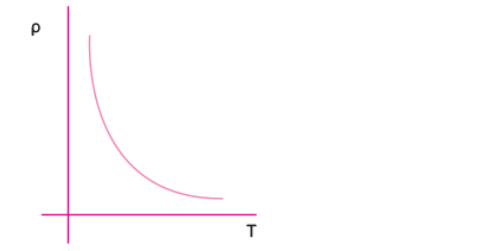
Q. 2. Sketch a graph showing the variation of resistivity of carbon with temperature.
OR
Plot a graph showing temperature dependence of resistivity for a typical semiconductor. How is this behaviour explained? [CBSE Delhi 2012, (F) 2011]
Ans. The resistivity of a typical semiconductor (carbon) decreases with increase of temperature. The graph is shown in figure.
Explanation: In semiconductor the number density of free electrons (n) increases with increase in temperature (T) and consequently the relaxation period decreases. But the effect of increase in n has higher impact than decrease of τ. So, resistivity decreases with increase in temperature.
Q. 3. (a) You are required to select a carbon resistor of resistance 47 kΩ ± 10% from a large collection. What should be the sequence of colour bands used to code it?
(b) Write the characteristics of manganin which make it suitable for making standard resistance. [CBSE (F) 2011]
Ans. (a) 47 kΩ ± 10% = 47 x 103Ω ± 10%
Sequence of colour should be: Yellow, Violet, Orange and Silver
(b) (i) Very low temperature coefficient of resistance.
(ii) High resistivity
Q. 4. Plot a graph showing variation of voltage Vs the current drawn from the cell. How can one get information from this plot about the emf of the cell and its internal resistance? [CBSE (F) 2016]
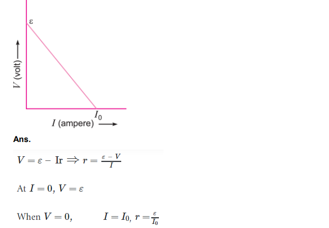
The intercept on y-axis gives the emf of the cell. The slope of graph gives the internal resistance.
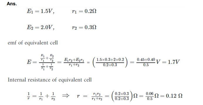
Q. 5. Two cells of emfs 1.5 V and 2.0 V having internal resistances 0.2Ω and 0.3Ω respectively are connected in parallel. Calculate the emf and internal resistance of the equivalent cell. [CBSE Delhi 2016]
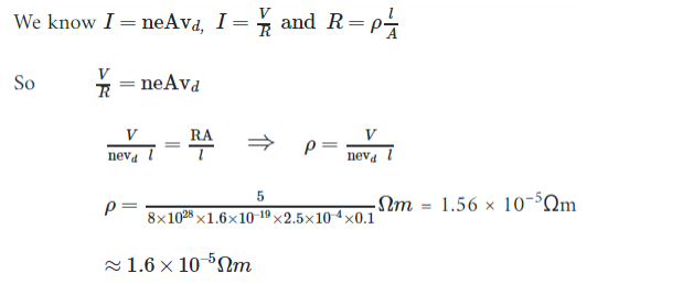
Q. 6. When 5 V potential difference is applied across a wire of length 0.1 m, the drift speed of electrons is 2.5 × 10⁻⁴ m/s. If the electron density in the wire is 8 × 1028 m–3, calculate the resistivity of the material of wire. [CBSE (North) 2016]
Ans.
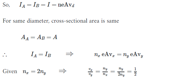
Q. 7. Two conducting wires X and Y of same diameter but different materials are joined in series across a battery. If the number density of electrons in X is twice that in Y, find the ratio of drift velocity of electrons in the two wires. [CBSE (AI) 2011]
Ans. In series current is same,
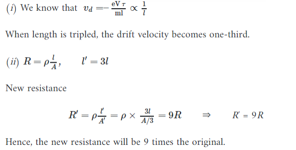
Q. 8. A conductor of length ‘l’ is connected to a dc source of potential ‘V’. If the length of the conductor is tripled by gradually stretching it, keeping ‘V’ constant, how will (i) drift speed of electrons and (ii) resistance of the conductor be affected? Justify your answer. [CBSE (F) 2012]
Ans.
Q. 9. A potential difference V is applied across the ends of copper wire of length l and diameter D. What is the effect on drift velocity of electrons if [CBSE Ajmer 2015]
(i) V is halved
(ii) l is doubled.
(iii) D is halved.

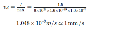
Q. 10. Estimate the average drift speed of conduction electrons in a copper wire of cross-sectional area 1.0 × 10⁻⁷ m2 carrying a current of 1.5 A. Assume the density of conduction electrons to be 9 × 1028 m–3. [CBSE (AI) 2014]
Ans. Flow of current in the conductor due to drift velocity of the free electrons is given by
I = neAvd
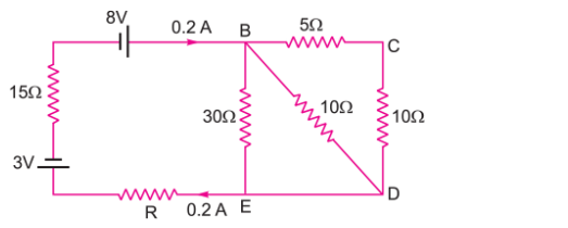
Q. 11. Use Kirchhoff’s laws to determine the value of current I1 in the given electrical circuit. [CBSE Delhi 2007]
Ans. From Kirchhoff’s first law at junction C
I3 = I1 + I2 …(i)
Applying Kirchhoff’s second law in mesh CDFEC
40I3 – 40 + 20I1 = 0 or 20 (2I3 + I1) = 40
⇒ I1 + 2I3 = 2 …(ii)
Applying Kirchhoff’s second law to mesh ABFEA
80 – 20I2 + 20I1 = 0
⇒ 20 (I1 – I2) = – 80
⇒ I2 – I1 = 4 …(iii)
Substituting value of I3 from (i) in (ii), we get
I1 + 2(I1 + I2) = 2 ⇒ 3I1 + 2I2 = 2 …(iv)
Multiplying equation (iii) by 2, we get
2I2 – 2I1 = 8 …(v)
Subtracting (v) from (4), we get
5I1 = – 6
I1 = -6/5 A = -1.2 A
Q. 12. State the underlying principle of a potentiometer. Write two factors by which current sensitivity of a potentiometer can be increased. Why is a potentiometer preferred over a voltmeter for measuring the emf of a cell? [CBSE Patna 2015]
Ans. Principle: The potential drop across a part of the potentiometer wire is directly proportional to the length of that part of the wire of uniform cross section.
V = kl
Where k is potential gradient.
Current sensitivity of potentiometer wire is also known as potential gradient, and it can be increased.
(i) By increasing the total length of the wire, keeping terminal voltage constant.
(ii) By connecting a suitable extra resistance R in series with the potentiometer. So, less amount of the current flows through the potentiometer wire.
Reasons: At the balance point, there is no net current drawn from the cell, and cell is in open circuit condition. Voltmeter has some resistance, when connected across the cell.
Some current is drawn, as a result emf of the cell decreases. Hence, emf of the cell cannot be measured by the voltmeter.
Q. 13. Answer the following:
(i) Why are the connections between the resistors in a meter bridge made of thick copper strips?
(ii) Why is it generally preferred to obtain the balance point in the middle of the meter bridge wire?
(iii) Which material is used for the meter bridge wire and why? [CBSE (AI) 2014] [HOTS]
Ans. (i) A thick copper strip offers a negligible resistance, so does not alter the value of resistances used in the meter bridge.
(ii) If the balance point is taken in the middle, it is done to minimise the percentage error in calculating the value of unknown resistance.
(iii) Generally alloys magnin/constantan/nichrome are used in Meter Bridge, because these materials have low temperature coefficient of resistivity.
Q. 14. Two students ‘X’ and ‘Y’ perform an experiment on potentiometer separately using the circuit given.
Keeping other parameters unchanged, how will the position of the null point be affected if
(i) ‘X’ increases the value of resistance R in the set-up by keeping the key K1 closed and the key K2 open?
(ii) ‘Y’ decreases the value of resistance S in the set-up, while the key K2 remain open and the key K1 closed? Justify your answer in each case. [CBSE (F) 2012] [HOTS]
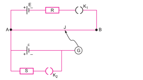
Ans. (i) By increasing resistance R the current through AB decreases, so potential gradient decreases. Hence a greater length of wire would be needed for balancing the same potential difference. So the null point would shift towards B.
(ii) By decreasing resistance S, the current through AB remains the same, potential gradient does not change. As K2 is open so there is no effect of S on null point.
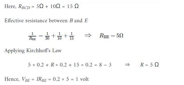
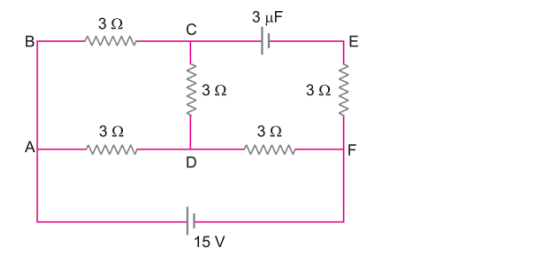
Q. 15. Calculate the value of the resistance R in the circuit shown in the figure so that the current in the circuit is 0.2 A. What would be the potential difference between points B and E?[CBSE (AI) 2012] [HOTS]
Ans.